Movements and Lunar Phenomena
Like all the celestial objects,the Moon also rotates around its polar axis. Like all satellites,the Moon also spins around its own planet,the Earth. But seen from down here,the movement of the Moon is truly complicated and gives rise to phenomena which have always aroused amazement.The rotation and its consequences
The Moon rotates around its own polar axis: with respect to the plane of revolution,the axis is inclined about 5 degrees.Since the period and direction of rotation are equal to the period and direction of revolution, the Moon always exposes the same half to the Earth: a phenomenon due to the Earth's attraction which,as Lagrange demonstrated in 1764,has slowed down the original lunar rotation.
The revolution and its consequences
The orbit which the Moon follows around the Earth is approximately an ellipse,of which the Earth occupies one of its foci. The motion takes place from West to East,in the same direction as the rotation and revolution of the Earth The lunar revolution period,i.e. the time interval between two passages of the Moon through the same point, of the orbit,also called "sidereal month", has a duration of 27.32 mean solar days.The lunar plane of revolution is inclined with respect to the ecliptic by an angle which varies 20 minutes around 5 degrees.The two points where the Moon's revolution plane and the ecliptic meets are called "nodes". When the moon is on the nodes, the Sun,moon,and the Earth are in the same plane , and depending on the relative locations, Solar or Lunar eclipses can happen.
The most common thing which is caused by the revolution of the moon is the changing phase of the Moon.
The Lunar Phases
The Lunar Phase Model
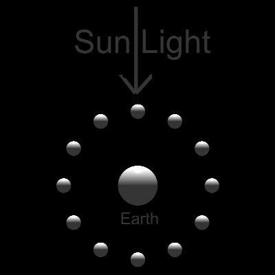 The simple model assumes the Earth and Moon in the same plane.
The sun light is so distance that during the Moon's rotation around the Earth
the light is uniform and parallel.
The simple model assumes the Earth and Moon in the same plane.
The sun light is so distance that during the Moon's rotation around the Earth
the light is uniform and parallel.
The model is made up of 12 moons placed equally spaced around the Earth.
The viewer is on the dark side of the Earth looking at the center of the Moon
**********lunar_phase_model.dwg**********
To create this drawing:
#1 Just download lunar_phase_model.dwg and render.
light direction data is already in the dwg file
#2 From scratch using AutoLISP program
Load lunar_phase.lsp (load "lunar_phase")
Then from command line, type (setup_lunarphase)
Thiw will create 12 moons around the global coordinate (0 0 0).
You can add a sphere of radius 2.0 at this center point to represent the Earth.
In AutoCAD, issue LIGHT command and define the distant light coming from direction (0 1 0)
Then use RENDER to render the drawing.
The Lunar Phase illustration done by ACAD
Program name: Lunar_Phase.lsp
Command : Lunar_phase
******************************lunar_phase_screen.dwg******************************
To create this drawing:
#1 Just download lunar_phase_screen.dwg and render.
light direction data is already in the dwg file
#2 From scratch using AutoLISP program
Load lunar_phase.lsp (load "lunar_phase")
Then from command line, type lunar_phase
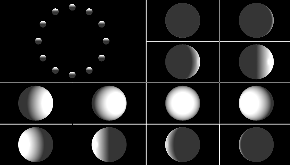
This will create 12 moons around the global coordinate (0 0 0), and 12 viewports,each of which
is a zoomed picture of the moon in each position vewed from the Earth.
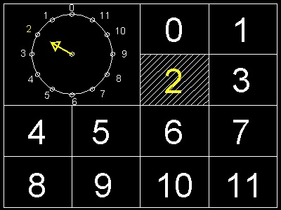
The numbers from 0 to 11 in the viewports in the following drawing corresponds to the numbers of
the Moon's position.
********lunar_phase_viewport.dwg********
In AutoCAD, issue LIGHT command and define the distant light coming from direction (0 1 0)
Then use RENDER to render the drawing.
The Lunar Phases Animation
Lunar Phases, starting from a New Moon, then First quarter, Full moon, Waning quarter, are shown in animation.
To create this animation:
After all the moons are rendered, go to each viewport, and issue command "saveimg",
and save the image file in BMP format. So ,for example, moon_1.bmp, moon_1.bmp, ... ,moon_11.bmp
will be created. Then call up PaintShop program and create animation as a slide .
References
Go to Fun_Math Content Table Earth Moon & Sun
All comments should be sent to Takaya Iwamoto
Last Updated July 9-th, 2006
Copyright 2006 Takaya Iwamoto All rights reserved.